Orange: the hands-on build, weeks 7 to 13. Bar lengths are to scale in weeks.
O-Wind Turbine · SRM IST · IJRTE 2019
04 / 17
Working principle
Tapered fins use Bernoulli's principle to turn the rotor
LARGER END: AIR ENTERS
SMALLER END: AIR SPEEDS UP
Schematic of the principle, not to scale. Longer arrows mean faster air.
Each fin is larger at one end than the other. The fins are equally spaced and inclined at an angle.
Air entering the larger end speeds up toward the smaller end, and that faster flow pushes the turbine round.
Blades are tilted so the rotor starts without an initial push, from the starting speed of the wind.
O-Wind Turbine · SRM IST · IJRTE 2019
05 / 17
Design
Designed in SolidWorks, built to exact dimensions
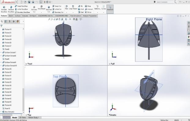
From sketch to model
A rough sketch became a 3D model in SolidWorks, and the parts were fabricated to its exact dimensions.
Rotor
8 blades, 4 inner and 4 outer. Fins between them act as spacers and supports.
Shaft
125 mm long: 24 mm diameter for the top 50 mm, 20 mm below. Cross-drilled to mount the generator.
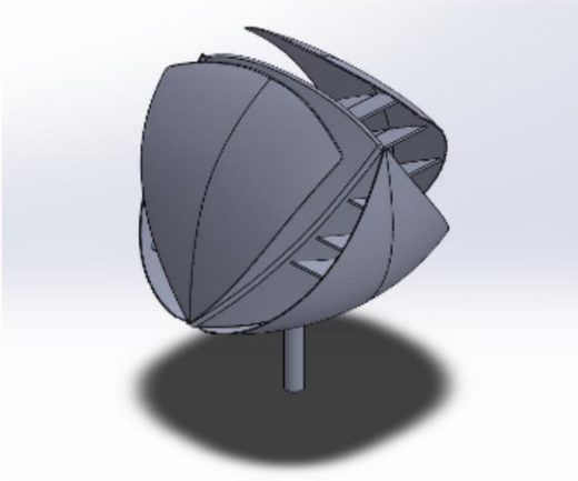
3D design of the turbine in SolidWorks
O-Wind Turbine · SRM IST · IJRTE 2019
06 / 17
Design calculations
Sizing the turbine: power, speed and torque
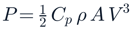
P power
A swept area
V wind speed
N rotor speed, rpm
ω angular velocity
T torque
D, R rotor diameter, radius
Cp power coefficient
2× wind speed = 8× power
Power grows with the cube of wind speed, which is why a turbine for light wind must make the most of every bit of flow.
1.225
kg/m³, air density ρ
0.4
power coefficient Cp
O-Wind Turbine · SRM IST · IJRTE 2019
07 / 17
Analysis
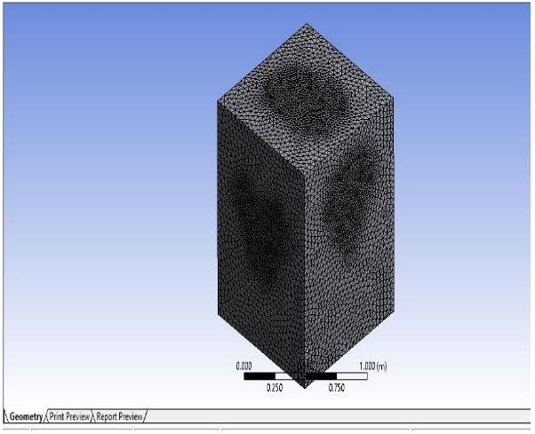
Flow around the blades, studied in ANSYS Fluent
Mesh of the flow domain
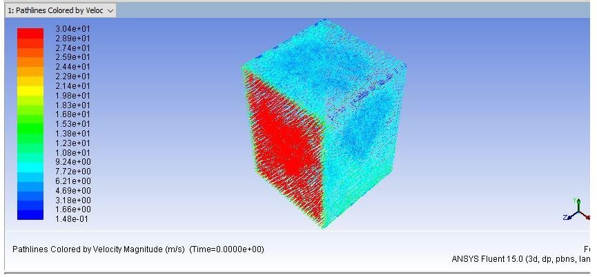
Velocity pathlines, colored by speed
SOLVER
Pressure-based
OBJECT
Blade assembly
FLUID
Air
INLET
Velocity inlet
OUTLET
Pressure outlet
WALLS
Enclosure surfaces
O-Wind Turbine · SRM IST · IJRTE 2019
08 / 17
Materials and components
Chosen for a light, strong, steady rotor
Component
Choice
Why
MDF board
600 × 600 × 16 mm, resin-bonded
Stronger than wood board; survives VMC machining
Glass fibre
Chopped strand mat in polyester resin
Light and strong; does not break easily
Generator
Permanent-magnet, below the blades
Turns rotation into electrical output
Battery
Lead-acid
Stores the charge from the generator
Bearings
Ball + self-aligning plummer block
Smooth rotation; corrects shaft wobble itself
Shaft
125 mm long, 24 / 20 mm diameter
Connects stand, turbine and generator
Trade-off: blades and fins must be light to turn freely, but top-grade glass fibre costs more. Low-wind output also calls for a capable, and so larger and heavier, generator.
O-Wind Turbine · SRM IST · IJRTE 2019
09 / 17
Mold blocks
Four machined MDF blocks became the molds
Block
L × B × T (mm)
Outer part, right and left
560 × 480 × 110
Inner part, front and back
490 × 550 × 70
Inner part, right and left
500 × 550 × 130
Outer part, front and back
500 × 600 × 180
Each block is a stack of 16 mm boards, from 32 boards of 600 × 600 mm, bonded and then machined to shape.
Center part a solid in four pieces
Outer shells thin sheets
Intermediate blades between the two
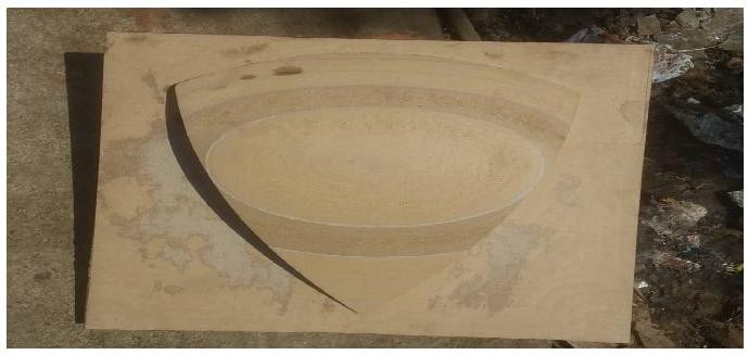
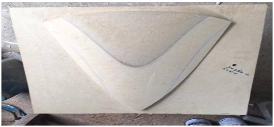
A machined MDF block
O-Wind Turbine · SRM IST · IJRTE 2019
10 / 17
Fabrication
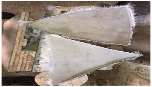
Blades cast in glass fibre from machined molds
01 BOND
32 MDF boards glued with polyester resin into 4 blocks
02 MACHINE
Blade shapes cut on a CNC vertical machining center
03 MOLD
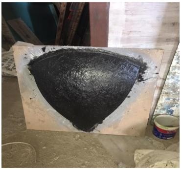
Glass fibre and resin over the master, dried 24 h or more
04 CAST
Blades laid up in the main mold, dried 24 to 36 h
05 FINISH
Trim excess, grind sharp edges, check the curve profile
Machined MDF master
Making the mold
Cast blades
O-Wind Turbine · SRM IST · IJRTE 2019
11 / 17
Assembly
From blades to a charged battery
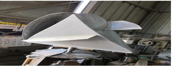
Fins bonded to the inner blades
Fins cut from glass-fibre sheet are bonded to the inner blades at the design angles; the outer blades go on over them.
The shaft runs from the rotor bush through a ball bearing and a plummer block to the generator.
A diode in the external circuit stops current flowing back from the battery.
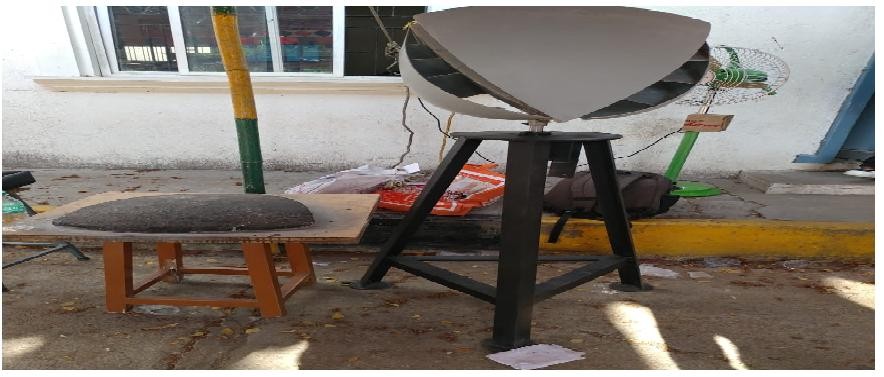
A tripod stand lifts the rotor clear of walls. It can also mount upside down or sideways.
Power path
Wind
any direction
Rotor
8 blades
Shaft
2 bearings
Generator
permanent magnet
Diode
one-way flow
Battery
lead-acid
Device
with a switch
O-Wind Turbine · SRM IST · IJRTE 2019
12 / 17
Testing
How the prototype was tested
Fin variants
Several fin angles and shapes were tried; the best arrangement was chosen before final assembly.
Natural and forced wind
Ambient wind, plus forced air from an air cooler or blower at different angles and distances.
Drive options
Generator run in direct drive, then with a 5× step-up gear. Several generators were tried.
Measured output
Output voltage measured with a multimeter to check the calculations and size the circuit.
What we learned
Early ambient wind was below stall speed, the minimum the turbine needs to start.
A blower's stream is narrow while natural wind is spread out, so angle and distance matter.
An off-center shaft makes the rotor wobble; careful centering and better bearings fixed it.
O-Wind Turbine · SRM IST · IJRTE 2019
13 / 17
See it turn
The finished turbine, spinning on its stand
Final assembly, 2019. Inner blades, fins and outer blades turn together as one rotor on the shaft and bearings.
49-second clip · press play
O-Wind Turbine · SRM IST · IJRTE 2019
14 / 17
Results
A working, compact prototype
Final prototype on its tripod stand
It works
The prototype turned in natural and forced wind and recharged a battery.
Low and high wind
Runs in low rated wind, and faster beside highways where passing vehicles push air past it.
Cheap to replicate
One mold makes many blades, so the turbine stays compact and cost-effective.
O-Wind Turbine · SRM IST · IJRTE 2019
15 / 17
Future scope
Next steps toward a household product
Aerofoil blades
Shape blades and fins as aerofoils to improve the aerodynamics.
Wind tunnel study
Measure torque, rpm, stall speeds, drag and full performance curves.
Custom generator
Built for low rpm, so the turbine is ready for use at home.
Lighter materials
Carbon fibre or nylon in place of glass fibre, without losing strength.
Flexible mounting
Hang it upside down or mount it sideways to fit more places.
New sites
Shorelines, roadsides and rural areas facing power shortages.
O-Wind Turbine · SRM IST · IJRTE 2019
16 / 17
Questions
Thank you
H. Mohammed Ali · S. Seetharam · S. Ashwin · M. S. Adithya
SRM Institute of Science and Technology, Chennai
“Design and Fabrication of O-Wind Turbine,” International Journal of Recent Technology and Engineering (IJRTE), Vol. 8, Issue 1, pp. 381–385, May 2019. Read the paper (PDF)
01 / 17
←→ keys or click the slide · F full screenTap or swipe the slide to move on